Content:
- Speed control bend
- Chicane and associated tables
- Example of chicane including cycle 'bypass'
- Junction tables
- Cross section of speed tables
- Vehicle speed control by development layout
- Traffic regulation orders
Where there are valid reasons why vehicle speeds cannot be controlled through site layout, and traffic calming measures are required, horizontal measures should be considered first and vertical measures used only as a last resort. Traffic calming measures should be in accordance with advice contained in the Department for Transport’s Local Transport Note 1/07 “Traffic Calming”, which also lists in Appendix A the relevant Traffic Advisory Leaflets.
Care should be taken over choosing traffic-calming measures for proposed bus routes, or where routes are likely to be used by the emergency services. (See Passenger Transport section).
While certain types of traffic calming (particularly vertical measures such as road humps) can have potential road safety benefits, they can also adversely affect the response times of emergency vehicles.
Design of speed control in new development
|
85th percentile design speed (mph) |
Maximum distance(b) (metres) |
|---|---|
| 30 | 150 |
| 25 | 100 |
| 20 | 60 |
| 15 | 40 |
(a) This is the maximum distance between junctions (where the flow of the road being designed must give way), 90-degree bends or other speed control feature
(b) Distance between curves is measured between the tangent points.
Vertical calming features should not be sited within 5m of the edge of a structure, for example, a bridge or culvert. Such features should also be sited clear of private accesses and driveways to avoid problems of vehicles ‘grounding’ as they turn into or out of the accesses or drives.
The council will consider other methods of vehicle speed control in the light of practical experience of their effectiveness and any further research. However, because of problems with noise and vibration, ‘rumble strips’ will not be accepted within development.
Speed cushions are normally preferred for residential distributor roads. However, if road humps are the only solution, these should be a maximum of 65mm in height (75mm subject to agreement) and a minimum of 8m in length. All traffic calming installed on the existing road network as part of a s278 agreement should include a speed reduction feature prior to any vertical feature where the 85th percentile approach speed is greater that 30mph.
Examples of speed control features
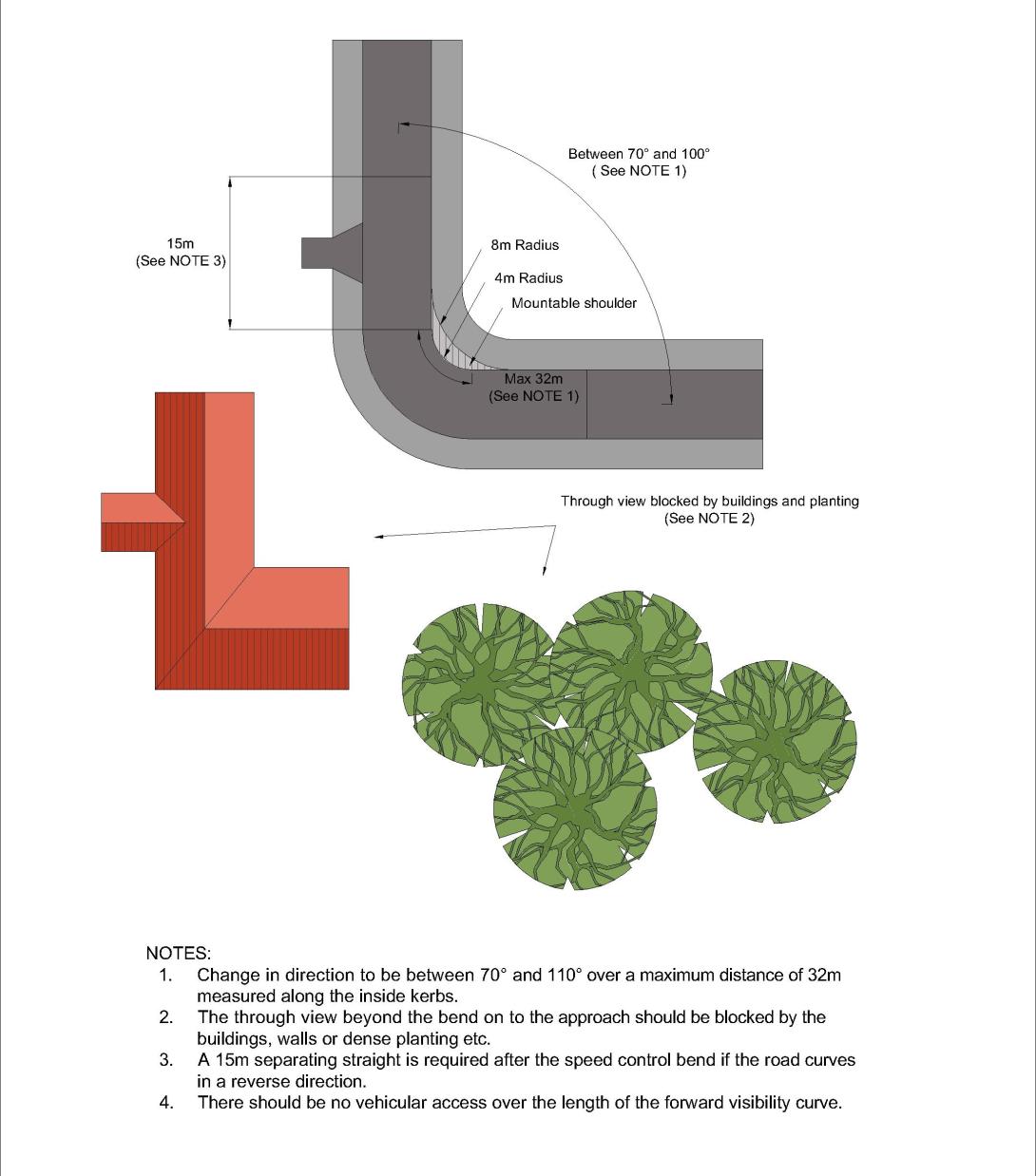
Figure 27: Speed control bend
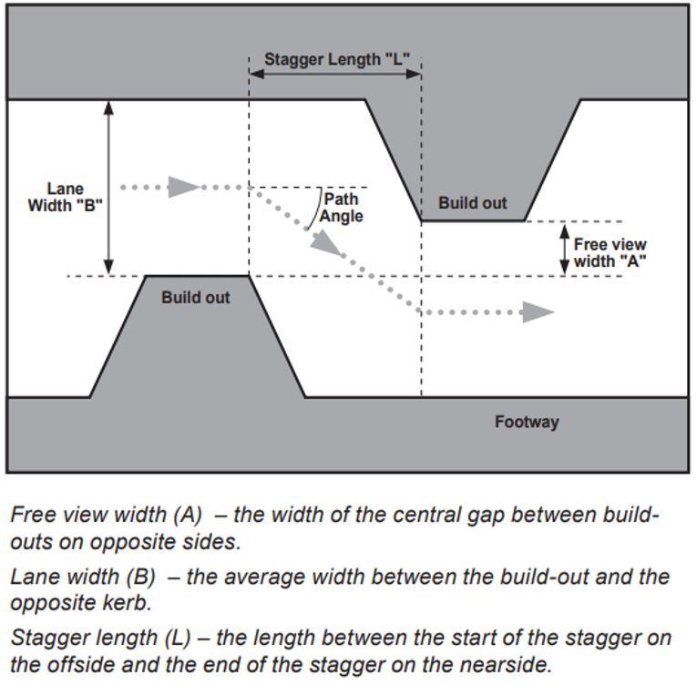
Figure 28: Chicane and associated tables (From the Department for Transport’s Local Transport Note 1/07 “Traffic Calming”)
| Lane width 'B' (metres) | Free view width 'A' (metres) | Stagger length 'L' to achieve required vehicle speed in chicane (metres) | Lane width 'B' (metres) | Free view width 'A' (metres) |
|---|---|---|---|---|
| 15 mph | 20 mph | 25 mph | ||
| 3.0 | +1.0 | 6 | 9 | 14 |
| 0.0 | 9 | 13 | 18 | |
| -1.0 | 12 | 16 | - | |
| 3.5 | +1.0 | - | - | 11 |
| 0.0 | 9 | 12 | 15 | |
| -1.0 | 11 | 15 | 19 | |
| 4.0 | +1.0 | - | 7 | 9 |
| 0.0 | - | 9 | 12 | |
| -1.0 | - | 11 | 15 |
| Lane width 'B' (metres) | Stagger length 'L' needed for a free view width of 0.0 (metres) | ||
|---|---|---|---|
| Articulated lorry | Rigid lorry | Single-deck bus | |
| 3.0 | 20 | 12 | 13 |
| 3.5 | 15 | 9 | 11 |
| 4.0 | 11 | 7 | 9 |
| Vehicle type | Vehicle dimensions | ||
|---|---|---|---|
| Width | Length | Wheelbase | |
| Articulated lorry | 2.5 | 16.1 | - |
| Rigid lorry | 2.5 | 9.2 | 5.8 |
| Single-deck bus | 2.5 | 11.8 | 5.5 |
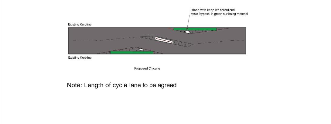
Figure 29: Example chicane including cycle bypass
Local Transport Note 1/20 "Cycle Infrastructure Design" (LTN 1/20) encourages the use of cycle bypasses alongside horizontal measures such as chicanes or lane narrowing. The gap should be at least 1.5m wide and be designed to allow access by standard sweeping machinery. The bypass arrangement should minimise conflict with motor vehicles when cycles re-enter the carriageway. The length of cycle lane must be agreed with the council.
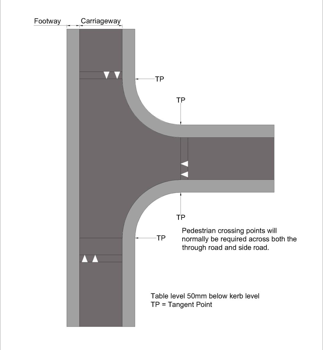
Figure 30: Junction table
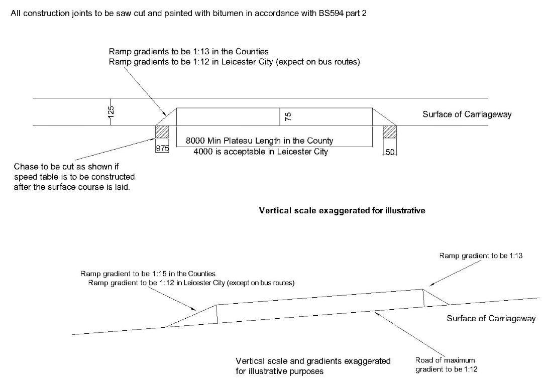
Figure 31: Cross section of speed tables (alterations for steep roads shown in lower diagram)
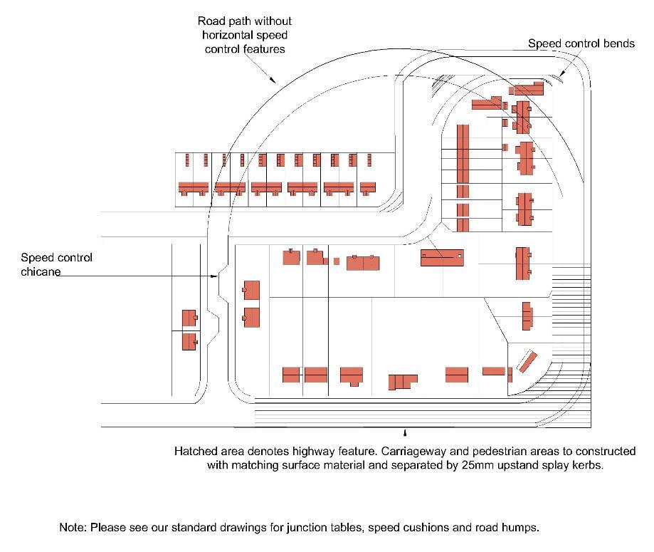
Figure 32: Example of vehicle speed control by development layout
Note: Please see the council’s standard drawings for junction tables, speed cushions and road humps.
Traffic regulation orders
Where a development requires changes to an existing Traffic Regulation Order (TRO) or a new order is required, the developer is required to pay all costs, including all consultation and legal costs. TROs are subject to statutory procedures and consultations. This can be a very lengthy process and a successful outcome is not guaranteed. Advice should be sought on the likely timescale and this should be considered when programming proposals.