Content
For proposed internal development roads, the visibility splay should be based on an assessment of likely 85th percentile vehicle speeds. For existing roads, it should be based on measured 85th percentile vehicle speeds. Where information does not exist, the council requires the developer to conduct surveys in line with the Data Collection section.
Manual for Streets (MfS) provides guidance on the use of calculated values for Stopping Sight Distances (SSD), for which clause 10.1.3 of MfS states are suitable for streets where the 85th percentile vehicle speeds are up to 60kph (37mph).
Assessing visibility
The council therefore allows for calculated SSDs to be used for 85th percentile vehicle speeds up to and including 60kph (37mph), and for vehicle speeds above this the Design Manual for Roads and Bridges (DMRB) is to be used.
While considering the design speeds in Tables 3 and 4, the council will assess visibility requirements based on likely vehicle speeds within a proposed development. Where it can be demonstrated that speeds are, in practice, likely to be lower than the design speeds, correspondingly shorter splays may be acceptable. Equally, if speeds are likely to be higher, the splays will need to be correspondingly greater in length.
|
Assessed likely vehicle 85th percentile vehicle speed (mph)
|
Measured 85th percentile vehicle speed (mph) |
Visibility distance at junctions, bends and vertical crests (m) Light vehicles |
Visibility distance at junctions, bends and vertical crests (m) HGV |
|---|---|---|---|
| 15 | 11 to 15 | 17 (a) | 19 (a) |
| 20 | 16 to 20 | 25 (a) | 27 (a) |
| Speeds on new residential development roads should normally be controlled to 20mph or less (b) | 21 to 25 | 33 (a) | 36 (a) |
| 26 to 30 | 43 (a) | 47 (a) | |
| 31 to 35 | 54 (a) | 59 (a) | |
| 36 to 40 | 65 (a) | 73 (a) | |
| 41 to 44 | 120 (b) | 120 (b) | |
| 45 to 53 | 160 (b) | 160 (b) | |
| 54 to 62 | 215 (b) | 215 (b) | |
| 63 to 75 | 295 (b) | 295 (b) |
(a) Based on the Manual for Streets documents, ‘adjusted for bonnet length’
(b) Based on DMRB, desirable minimum criteria for deceleration rate (0.25g) and reaction / perception time (2 seconds). The application of a higher standard value for deceleration rate and a lower standard value for reaction time would need to be based on a robust evidenced justification for the location under consideration to be agreed with the council.
Calculated values will be accepted for actual agreed 85th percentile speeds.
Where speed is assessed to be over 20mph, splay provision will normally be based on the appropriate measured 85th percentile vehicle speed distance.
For all road types within a development, visibility (at junctions, bends or crests) in the vertical plane should normally be measured from a driver’s eye-height of no less than 1.05m above the road surface to a point no less than 0.6m above the road surface. On roads outside of the development, for example at the site access, the visibility should be measured from an eye-height of not less than 1.05m to a point not less than 0.26m, in line with the DMRB. However, if roads fall within the definition of a road (street) as defined in "Road design and layout", visibility can be measured as if the road lies within a development.
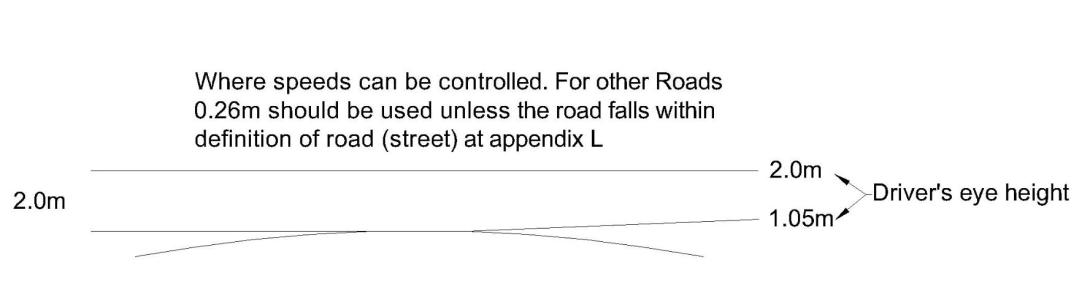
Figure 6: Crests in road (brow of hill)
Designing of visibility splays
For all horizontal visibility splays, the rear of a footway, cycleway or similar should coincide with (match) the rear edge of the visibility splay. A more accurate assessment of visibility splay is made by measuring to the nearside edge of the vehicle track. The measurement is taken from the point where this line intersects the centreline of the minor arm unless there is a splitter island in the minor arm.
Figure 7 shows an offset visibility splay 1m from the kerbline. Whilst this does not conform to MfS or DMRB requirements (which require no offset), it represents a permitted relaxation under LHDG guidance.
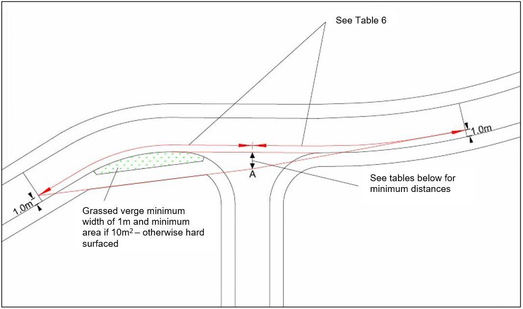
Figure 7: Visibility at junctions
The required set back will depend on scale and nature of proposed development. The council will accept a minimum set-back distance of 2.4m (i.e. to point ‘A) unless a greater set-back distance is required for junction capacity reasons. A 4.5m set-back will be required for all major industrial access roads and for those minor industrial access roads where the scale of development and volume/nature of traffic movements dictate it necessary
Developers should refer to DMRB CD123 Clause 3.9, where the junction is on the outside of a bend.
Evidence that the correct vertical visibility can be provided for the junction visibility splay will also be required. This should be achieved by producing a long section along the line of the visibility splay.

Figure 8: Designing bends
Widening at Bends
On residential roads serving more than 25 dwellings, carriageways should be widened at bends that curve through more than 10 degrees.
| Centre-line radius (m) | 20 | 30 | 40 | 50 | 60 | 80 |
|---|---|---|---|---|---|---|
| Minimum widening | 0.60 | 0.40 | 0.35 | 0.25 | 0.20 | 0.15 |
Bends should be widened in industrial and commercial developments.
| Centre line radius (m) | 55 to 74 | 75 to 89 | 90 to150 |
|---|---|---|---|
| Minimum widening | 1.2 | 0.7 | 0.6 |
For any proposals not conforming to the figures in the above tables, vehicle swept path analysis must be produced to show that the proposed layout can accommodate appropriate vehicles without danger to other road users, including pedestrians and cyclists. There should be no overrunning of the centreline or kerbline and no overhanging of footways by vehicles.